Introduction: What is photogrammetry? Why did we decide to use it?
Photogrammetry, also known as Image Based Modeling or Structure from Motion (SfM) is a 3D modeling process that allows you to build digital models of objects. It is a highly versatile procedure that can process small objects, large sites, or in our case, a house. Using images captured from devices as simple as iPhones to drone imagery, these images are processed in software that align images, create points clouds, and add mesh to digitize the object of interest. Given the accessibility and ease of use of this software, photogrammetry is becoming an increasingly popular form of documentation for archaeological sites, artifacts, heritage management, and conservation efforts. We decided to use photogrammetry to model the modern-day Seccombe House because it contributes to how we can interpret our findings and present them to the public. Although the house has undergone many changes over the years, it is still the Seccombe House and stands as a piece of Carleton College’s history. The models that we were able to generate through photogrammetry give us an idea of how the house has evolved over time and they are easy to share with others.

Access the scan here: https://sketchfab.com/3d-models/seccombe-house-67888e2b1bfc49338f922958687d3fc9.
Methods:
Image capture
In order to begin work on the model, we first had to gather images of the Seccombe House for the scan. Between the phone cameras and drone, we took approximately 1,600 photos to work with in the software. Phone cameras were used to capture ground level images of the sides of the house, while the drone was used to take photos of the roof. In general, images for photogrammetry must follow a number of basic guidelines in order to produce adequate final scans. They are as follows:
- Consistent lighting
- Avoid long shadows or intense glare. If needed, use an umbrella to shield the camera from light.
- Consistent focal length
- Do not zoom in or zoom out while taking photos.
- Overlapping photos
- When capturing images, aim for 60-80% overlap.
Image Selection:
After photos were captured, the images were then sorted through to find optimal images to process. We removed blurry images as well as close up photos. Though close up images are completely fine for smaller scans, when dealing with such a large object such as a house, we found that it was considerably more difficult for the software to align these photos.
Creating the 3D Model Using Agisoft Metshape:
Creating the 3D Model Using Agisoft Metshape:
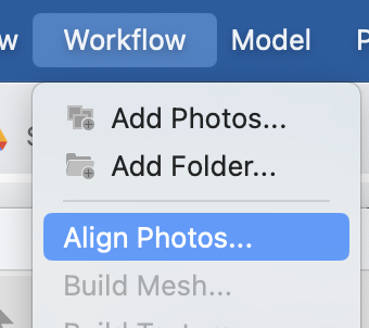
- Upload images (workflow → add photos → select desired images or folder)
- First, images are uploaded to Agisoft metashape. Scans can be created as one “chunk” or as multiple “chunks.” In the case of our scan, it was created in multiple chunks.


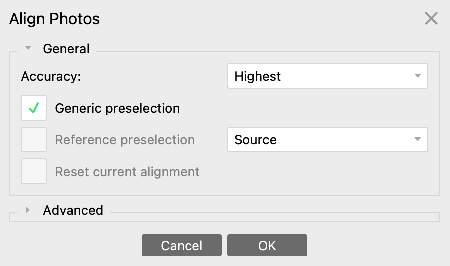
- Align images (Workflow → Align photos)
- Most of the time, alignment will go over easily. If issues arise and the images cannot be aligned, the non-aligned images will be listed as “NA.” These can be removed manually, or aligned manually. If there is substantial overlap, removing a few of the images that cannot align should not be a problem.
- Repeat for each chunk.
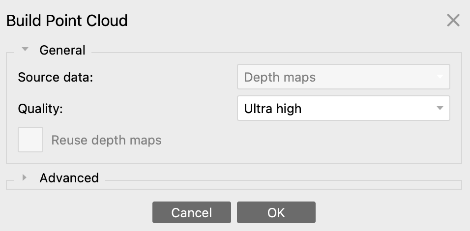
- Build point cloud (Workflow → Build Point Cloud)
- Repeat for each chunk.
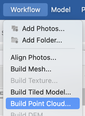
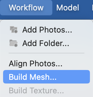
- Build Mesh (Workflow → Build Mesh)
- Repeat for each chunk.
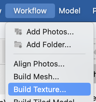
- Build Texture (Workflow → Build Texture)
- Repeat for each chunk.
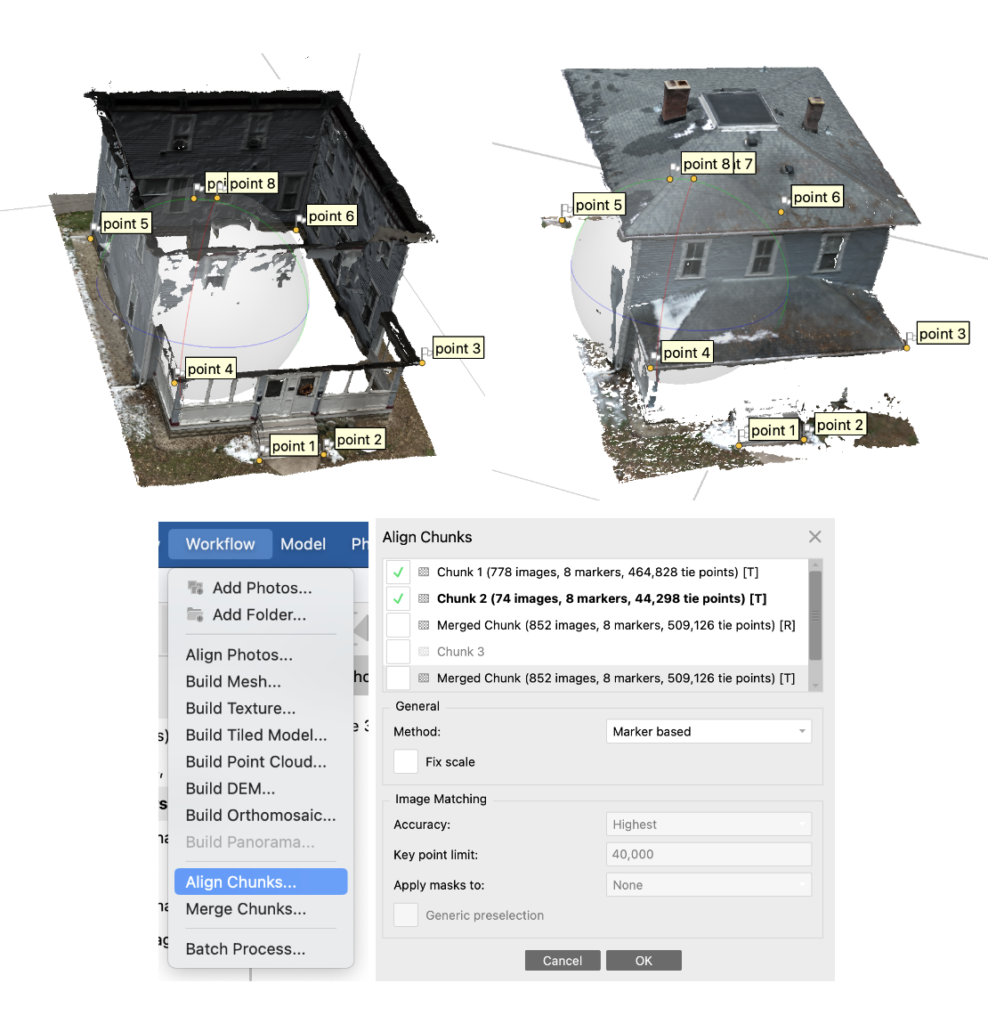
- Align Chunks (Workflow → Align Chunks → Point Based Alignment of Marker Based Alignment)
- If your model was built out of multiple chunks, you will need to align the chunks. There are two ways that this can be done. First, you can use the software by selecting “Align Chunks” and processing the model. This was not working for our model, so we chose to align it manually.
- Manual alignment: Place markers on specific places on the model. These should be placed in the same exact places on each chunk. Make sure the marker number is the same for each chunk. For example, Marker 4 will be placed on the bottom left corner of the roof for both Chunk 1 and 2.
- Go to the “align chunks” tab and select “marker based alignment.
- Here is a brief youtube tutorial is quite helpful: https://www.youtube.com/watch?v=WjzQ25j7OHA.
- If your model was built out of multiple chunks, you will need to align the chunks. There are two ways that this can be done. First, you can use the software by selecting “Align Chunks” and processing the model. This was not working for our model, so we chose to align it manually.
- Cleaning Up Model (Show aligned chunks → Selection → Delete unwanted data)
- Turn on the “Show Aligned Chunks” tool. It will be in the top right-hand corner of your screen.
- See where data is overlapping in your aligned model.
- Select which chunk you would like to remove specific data from in the workspace tab.
- Remove data using the highlight and delete tools.
- Continue process, removing unwanted data, and deleting stray components not wanted in final scan
- Refer to the tutorial above for more detailed/visual instruction of this process.
- Merge Chunks (Workflow → Merge Chunks)
- Merge aligned chunks.
- Export as .OBJ file (File → Export → Export Model)
3D Printing:
After our model was finished in Agisoft Metashape, we exported the file and took it to the Makerspace here on campus. The model was made watertight and then printed. Aspects had to be adjusted in order to close the holes in the original mesh.
Upload to Sketch Fab:
In order to ensure public access to our work, we uploaded the model to sketch fab, a digital 3D model sharing platform. The scan can be accessed here: